


 |
Modular and Reconfigurable The key to success incustom solutions. |

AIR-COUPLED ULTRASOUND
The revolution in non-contact ultrasound systems, from a single channel to hundreds of channels.
")

|
Modular and Reconfigurable The key to success incustom solutions. |
 |
Training Personalized training courses. |
 |
ENGINEERING Feasibility study as a key of sucess. |
 |
ULTRASCOPE SERIE ULTRASCOPE USB,all the power of a high-end system in the palm of your hand. |
 |
DIFRASCOPE Much more than a multi-channel TOFD sustem. |
 |
AMPLUS-32 AMPLUS-32 is a broadband pre-amplifier fully compatible with ULTRASCOPE / DIFRASCOPE. |
 |
PHASED ARRAY SYSTEM Phased array systems,based on the SITAU technology. |
 |
GNR FILTER See beyond structural noise no matter grain noise present on the material. |
 |
AUTOFOCUS Get the best image quality with a single click... no matter how complex the geometry is. |
 |
FULL PARALLEL PHASED ARRAY Synthetic Aperture Techniques (SAFT), Full matrix capture (FMC), total focusing method (TFM), Sampled Phased array, can be implemented. |
 |
GPU Development Kit Complete your SITAU Phased-Array system with the power of GPU’s. |
 |
AIRSCOPE SOLUTIONS Air-coupled NDT solutions for compiste inspections. |
 |
AIRSCOPE MULTICHANNEL Air-coupled NDT solutions for compiste inspections. |
 |
AIRSCOPE PHASED ARRAY Unique in the world ,Non coupling Phased Array system. |
 |
Air-Coupled transducers Wideband transducers from 25Khz to 2 Mhz. Focus and Non-focus. |
 |
Ultrasound Scanners Fully compatible with ULTRASCOPE, DIFRASCOPE and SITAU products. |
 |
Inmersion Tank Wide range of immersion tanks for non-destructive testing in water bath. |
 |
Ultraview,Ultrascan & TOFD view Powerful software tools to easily cofigure the system parameters. |
 |
MotorMotion MotorMOTION is a fully programmable steppermotor control unit, capable of simultaneously controlling up to 3 axes, with configurable acceleration ramp and micro-steps. |
 |
Ultrasound- CALC, Phased Array-Wizard and TOFD-CALC A series of handheld tools for NDT, based on Android Operating System. |
 DASEL is a company specialized in the development of high-end ultrasound technology. We offer at the same time flexible solutions according to each client requirements. Therefore the quality level in our products has not been neglected. Quality is a commitment that DASEL applies in all production areas to maintain traceability of manufactured products. For this reason the company has been certified ISO 9001:2015 and ISO 9100:2018 by Bureau Veritas in the equipments production and calibration.
 DASEL develops all its products with a modular architecture and using high-density re-configurable devices (FPGAs). Given the high cost for new hardware development, this design philosophy allows to adjust our systems to many different applications, with the incorporation of new functions or specific algorithms with no need to upgrade the equipment electronics.
 |
 |
 |
 |
||
| ISO 9001:2015 | ISO 9100:2018 | ||||
|
PYME INNOVADORA
Válido hasta el 22 de febrero de 2022
 |

The project ULTRACOV aimed at developing a novel ultrasound scanner to face COVID-19 disease challenges: early diagnosis and following of patients evolution leaded by DASEL get funded by last CDTI call.
This project obtained funding from the las call of the Spanish Institution “CDTI” (July 2020) in a very competitive call for R&D projects to face the health emergency COVID19. ULTRACOV This development is led by DASEL SL, a Madrid SME based in Arganda del Rey. The Ultrasonic Systems and Technologies Group of the CSIC (GSTU-CSIC) and the Nuclear Physics Group Group of the Complutense University of Madrid (GFN-UCM) will also participate. The participation of the emergency ultrasound service of the Hospital Universitario La Paz guarantees the clinical approach at all stages of the development of the ultrasound system, and will carry out the first trials with patients.
The project duration is 18 months, (starting July 2020) and clinical trials of the prototype are planned to begin in early 2021.
The objective of the ULTRACOV project is the development of an ultrasound scanner oriented to the early detection and monitoring of the COVID-19 disease, specially designed for situations of pandemic and high healthcare pressure. Through interactive artificial intelligence tools that simplify the examination and interpretation of images, and a design oriented to operation in high-risk conditions (easy disinfection, ergonomics, etc.), the aim is to extend lung ultrasound to a greater number of professionals and services, from primary care to intensive care. The impact on the capacity of the healthcare system for the management of COVID-19 patients would be very positive, since it is a very specific tool for evaluating the lung condition at all stages of the disease, including potential chronic problems. in the medium and long term. Furthermore, it would be useful for the diagnosis and management of patients with other lung pathologies, potentially serious in certain groups (pediatric patients, pregnant patients, etc.).
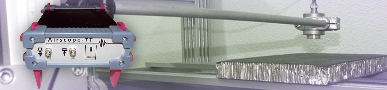
AirScope is a non-contact ultrasound inspection system that uses air as couplant between the transducer and the component under test. This feature eliminates the problems associated with water immersion and water jet:
- Water can flow into the component structure, especially in CFRP, laminates and mask the presence of some flaws like delaminations.
- Components inspected by water coupling usually have to be dry and cleaned afterwards, increasing production time.
- There are some components that cannot be wet:
o Some honeycomb structures
o Aerospace components
o Hydrophilic materials like non-cured composites.
AirScope technology was specifically designed to deal with ultrasound air-borne challenges:
- The huge impedance mismatch between air and any solid material introduces large insertion losses, which usually generate signals with poor SNR. Airscope transducers and electronics have been designed to maximize emission efficiency and reception sensitivity, providing the best possible SNR in most challenging scenarios.
- Pulse-echo inspection is virtually impossible because the large reflection coefficient (99.6%) generates a large interface echo that mast any defect inside the component. That is the reason why non-contact inspections are performed in through-transmission mode from both sides of the component.
On the other hand, the large velocity mismatch between air and solids generates strong refraction, and the critical angle for longitudinal waves is rather low (about 6º for CFRP) making alignment between transducers critical. High precision of AirScope mechanics warranties a total control of incidence angle, minimizing signal loss due to transducer misalignment.
- Increasing frequency increases attenuation in air. Although it is possible to manufacture transducer with -20dB sensitivity at 250 kHz, it is quite difficult to achieve -40 dB sensitivity at 1 MHz. Airscope transducers manufacturing technique allows focusing the beam at the component surface, maximizing the transmitted energy, sensitivity and resolution.
Different from CFRP monolithic components, honeycomb structures must usually be sealed when inspected by water coupling, to avoid water to flow into the part.
Airscope system allows inspecting this kind of parts without contact, maintaining the core integrity without sealing the component edges. Defects that can be detected include: delaminations, inclusions, crushed core, lack of adhesive, unbound, etc.
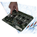
Test sample PRB-01 was inspected. Main features are:
- Aluminum core and 3 layer CFRP skins.

Fig. 1.- Pictures of PRB-01 test sample
- The test-sample is made of two zones with different core sizes:
o Left side with 1/4'' core
o Right side with 1/8'' core

Fig. 2.- Defects location of PRB-01 test-sample
Figures 3 and 4 compare the results obtained with Airscope (right) with those obtained with a standard non-contact system currently used in aerospace industry (left). Higher resolution and contrast of AirScope system is evident.

Fig. 3.- Results of the inspection of the ¼’’ core zone of the PRB-01 test sample. (left) with the standard system used in aerospace industry and (right) wit Airscope solution.

Fig. 4.- Results of the inspection of the 1/8’’ core zone of the PRB-01 test sample. (left) with the standard system used in aerospace industry and (right) wit Airscope solution.
A second test sample named PRB-02 was inspected. Main features are:
- Honeycomb structure with aluminum core and 4 layer CFRP skins.

Fig. 5.- Pictures of the PRB-02 test sample
- The sample is divided in two halves with different core sizes:
o Left side with 3/16'' core
o Right side with 1/8'' core

Fig. 6.- Defects location of PRB-02 test sample.
Figures 7 and 8 compare the results obtained with Airscope (right) with those obtained with a standard non-contact system currently used in aerospace industry (left). Higher resolution and contrast of AirScope system is again evident.

Fig. 7.- Results of the inspection of the 3/16’’ core zone of the PRB-02 test sample. (left) with the standard system used in aerospace industry and (right) wit Airscope solution.

Fig. 8.- Results of the inspection of the 1/8’’ core zone of the PRB-02 test sample. (left) with the standard system used in aerospace industry and (right) wit Airscope solution.
Conclusions are extracted from direct comparison of the obtained images, because no information is currently available of the measurement set-up and color-scale with the standard system. In all cases, better sensitivity and resolution is obtained with Airscope. Some details must be pointed out:
- In the left side of the PRB-01 test block an indication appear with the conventional system and not with Airscope. This indication is from a sticker that was removed between inspections. Furthermore, the indication in the top right of the image does not appear because scanning area was smaller with Airscope.

Fig. 9.- Detail of indications not present in the PRB-01 ¼’’ inspection with (left) Airscope and (right) conventional system
- The inspection of the 1/8’’ core side of PRB-01 evidences the higher resolution of the Airscope system. Smaller defects (6x6 mm) are clearly detected with a -12dB threshold, while with the conventional system are detected only marginally (Fig. 10).

Fig. 10.- PRB-01, core 1/8’’ : Resolution differences for the smaller defects of 6x6 mm (left) Airscope and (right) conventional system.
- In the 3/16’’ core zone of the PRB-02 test sample, higher resolution and contrast of Airscope system is also evident. An indication that is not present with the conventional system was due to a surface impact performed between inspections.

Fig. 11.- PRB-02 core 3/16’’ Comparison of resolution and contrast between inspections (left) Airscope and (right) conventional system.
- Inspection of the 1/8’’ zone of the PRB-02 test sample reveals the higher contrast of the Airscope system, detecting six defects that are hardly seen with the conventional system.

Fig. 12.- PRB-02 core 1/8’’ Comparison of resolution and contrast between inspections (left) Airscope and (right) conventional system.
Its reduced dimensions (50 x 100 x 170 mm) and weight allows mounting the Airscope system directly on the inspection head, avoiding noise problems associated with long wires. Its Ethernet connection eases integration into the plant communication infrastructure.
Airscope is the unique non-contact multi-channel system in the market that, depending on the number of active channels, allows increasing the inspection speed up to 8 times.
Inspection speed for a single-channel configuration is 500 mm/s with a resolution of 2mm.
SonoJet focused transducers, included with Airscope systems, have been specifically designed by the Spanish National Research Council (CSIC) for air-borne ultrasound applications.
|
Model |
SONOJET |
|
Spot size |
2 mm |
|
Beam width |
80% |
|
Focal distance |
50 mm |

Fig. 13.- Field simulation of the focused SonoJet transducers.
Airscope system has 8 physical pulse-echo multiplexed channels, which can be configured for sequential acquisition of up to 32 virtual channels. Each virtual channel can be configured to emit and receive with any of the 8 physical channels
Virtual channels are defined by assigning a connector number for emission and another for reception. A virtual channel can then emit and receive from the same connector (pulse-echo) or with different ones (pitch-catch or through-transmission). Physical connectors can be shared among virtual channels.

Fig 14.- Virtual channel configuration scheme
Operation parameters are independent for each one of the 32 virtual channels (pulse width, gain, filters, averaging, etc).
|
Pulser: |
Negative square wave pulse |
|
|
Excitation voltage |
Programmable -20 a -400 V |
|
|
Pulse width |
Programmable from 100 ns to 25 μs, with 10 ns resolution |
|
|
Fall time |
< 5 ns. |
|
|
Rise time |
< 15 ns. |
|
|
Pulse repetition frequency (PRF) |
20 KHz |
|
|
Burst mode |
Programmable, between 1 and 256 pulses |
|
|
Control signals |
Trigger sources and I/O signals |
|
|
Encoder inputs |
2 inputs, quadrature encoders |
|
|
I/O signals |
External trigger, sync output |
|
|
Acquisition modes |
Pulse-echo, through-transmission. Each one of the 8 physical channels can be configured as emitter, receiver of both (pulse-echo)
|
|
|
Automatic start acquisition or by threshold crossing (echo-start) |
|
|
|
Inspection range |
1. Sampling frequency > 25 MHzà 20.480 samples At maximum sampling frequency of 100 MHz, maximum range is 204,8 μs (~62 mm in air)
2. Sampling frequency < 25 MHzà 65.500 samples With a sampling frequency of 25 MHz, maximum range is 2620 μs (~786 mm in air) With a sampling frequency of 3 MHz, maximum range is 21833 μs (~6550 mm in air)
3. With EMI filter or averaging à 20.480 samples independently of the sampling frequency.
|
|
|
Initial delay |
Programmable up to 26 ms, with 100 ns resolution. |
|
|
Linearity |
± 1 dB |
|
|
Attenuator |
Programmable 0 dB / - 20 dB |
|
|
Cross-talk |
< -60 dB |
|
|
Amplifier: |
Wide-band and low-noise amplifier |
|
|
Gain |
Programmable from 0 to 100 dB |
|
|
Pre-amplifier (AMPLUS-32-LF) |
+32 dB |
|
|
Bandwidth (-3 dB) |
20 KHz to 2.5 MHz (-3 dB) |
|
|
Input protection circuit |
Low resistance MOSFET active circuit |
|
|
Maximum input signal |
5 Vpp |
|
|
Input impedance |
200 W |
|
|
Digital sampling |
Differential input A/D converters with LVDS output |
|
|
Resolution |
14 bits |
|
|
Sampling frequency |
100 MHz maximum |
|
|
Function of Time–Gain compensation (TGC): |
|
|
|
Gain range |
100 dB |
|
|
TGC |
Integrated TGC curve with programmable values |
|
|
Interval between DAC points |
Programmable from 100 ns y 25.6 us, with 100 ns steps. |
|
|
Time range |
Up to 105 ms depending on the temporal resolution TGC |
|
|
Trigger sources |
|
|
Internal by software |
|
|
Internal by PRF |
|
|
Encoder |
|
|
External Trigger |
|
|
Filters |
|
|
Anti-aliasing low-pass filter at 2.5 MHz (Bandwidth (-3 dB): 20 KHz to 2.5 MHz). |
|
|
Digital bandpass filter (See section 3.9) |
|
|
Digital signal processing |
Post-processing functions of the traces in real time. |
|
|
64 tap digital pass-band FIR filter, with arbitrary low-pass and high-pass frequencies. - Constant answer in the filter pass-band (ripple < 0.1 dB). - High attenuation out of the filter pass-band (typ. > -50 dB). |
|
|
|
Data format: 16 bits with sign |
|
|
|
Information registry in real time: A-scan, gates, peaks, encoders position. |
|
|
|
3 programmable gates for peaks detection - Alarm type : Positive / Negative - Initial / end times: Programmable from first to last acquired sample - Detection threshold Programmable (0 to 100 % of scale in screen) |
|
|
Programmable traces compression: ratios from 1:1 (no compression) to 128:1, without loss of information in peak amplitude and position. |
|
|
Programmable decimation from 1 to 4095 (equivalent to sampling frequencies from 24.42 kHz to 100 MHz).
|
|
|
Digital envelope detection (VIDEO output) by 64 taps Hilbert filter and CORDIC processor.
|
|
|
EMI-noise reject filter with 2 to 5 traces:
- Eliminates, in real time, impulsive noise. - Improves defect detection and reduce false positive indications. - Allow a large dynamic range in C/D Scan images in noisy environments.
|
|
|
Averaging. (2, 4, 8, 16, 32, 64, 128, 256) |
|
|
Power consumption |
7 W máx = 1100 mA (6 V), load 50 W, PRF=5 KHz, pulse amplitude -400 V. |
|
|
Power source |
100- 220 Volt 47- 63 Hz |
|
|
Temperature range |
0 ºC a 50 ºC (Ambient) |
|
|
Operative system |
Microsoft Windows 7, VISTA / XP / 2000 / 98SE |
|
|
Data interface |
Ethernet 100 Mbit/s. Connection with TCP/IP y UDP/IP. Sustained throughput: >7 MBytes/s. |
|
|
Internal memory for A-Scans |
48 MB (24 Msamples) |
|
- Simultaneous acquisition of several C/D Scans.
- Compatible with principal manufacturers normative
- A-Scan registry in C and D scans, with post processing capabilities like gate position change. Whole data cube available for analysis.
- Registry of encoder position and gates peaks during C and D scans.
- Evaluation of signal-to-noise ratio in C-Scan images.
Our inspection gantry system is based on a flexible structure that easily adapts to different dimensions, upon client requirement.
It is based of a solid structure with pre-mounted and electrowelded frame, with a high quality primer coat and oven-enamelled paint to avoid corrosion. It includes fixing points with levelers, with no need of specific ground foundation.
Its vertical configuration allows installing it in zones with restricted access, near vertical bulkheads, because access is required from one side only.

Its flexible architecture allows easily adapting the system to future client needs. Based on a solid structure, it can reach a size of 4x3 m, while it can be dimensioned for small systems down to 0.5 x 1m.
Regardless its dimension, the system is designed to easily perform inspections of components of different size and shape. It includes a frame holder with a longitudinal slot that allows easily loading different frames that hold the inspected part. This gives a high degree of flexibility, allowing the client to control the component fixation process in an easy and secure way.

Once loaded and fixed, the inspection can be done automatically of manually, allowing the operator to move the inspection head in any direction using a button panel, choosing the movement direction and speed. Also manual movements are motorized and monitored by encoders, so manual inspections can be registered.

Fully automated inspections are also possible by programming scanning trajectories for each component model.
Gantry robustness and flexibility of the frame-holder system is completed with a kinematic group made of synchronized and high precision linear guides with silent transmission.

Main features of the kinematic group are inspection speed up to 1 m/s and acceleration up to 10 m/s2. Repeatability is warranted by the high system capacity, which can handle dynamic loads above Cx 1.715 N and Cy 1.000 N, and dynamic moments of Mx 22 Nm and My 31 Nm, withstanding inertia and stress caused by the inspection head displacement.
System is driven by electrical motors with closed loop control with encoders, based on Ethernet communications. Combined precision of the control system and the kinematic group is of 0.1 mm of maximum deviation in any axe. Repeatability is 0.2 mm maximum into the holding frame.
Gantry is controlled by an intuitive graphical used interface in a touch-screen panel. It incorporates status information and an advanced support and maintenance help system.

Industrial Scanners
Aerospace Inspection Solutions
Flaw Detectors
Ultrasonic Flaw Detectors
Phased Array
Guided Wave
Pulser-Receivers
Integrated Inspection Systems
Bar Inspection Systems
Tube Inspection Systems
NDT Systems Instrumentation
Advanced NDT applications
GLASSFIBER BROKEN FIBERS
GLASSFIBER UNBOND
RAILWAY STEEL BOLTS
CASTING INCLUSIONS
AUTOMOTIVE NODULARITY
Applications
Application Notes
Applications Support
PDF Library
Video Gallery
Software Downloads
Training Academy
Obsolete Products
ISO Certifications

